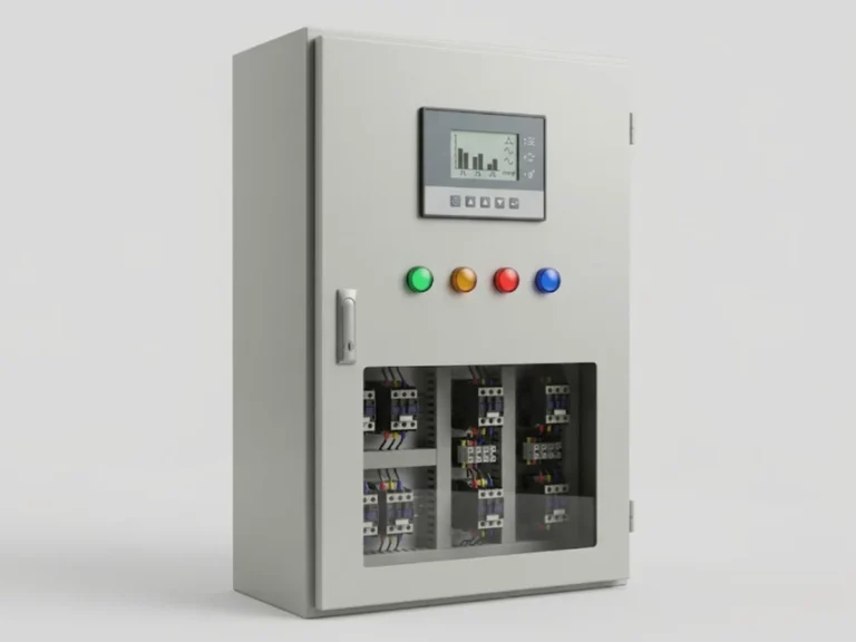
An APFC panel (automatic power factor correction panel) holds a factory’s power factor close to unity by switching capacitors in and out as the load changes. A fixed capacitor bank is fine for a steady load. Most plants, however, have motors, welders and drives that change all day, and a fixed bank then overcorrects at light load. The APFC panel solves that with a controller that watches the line and adds or drops capacitor steps.
What is inside an APFC panel
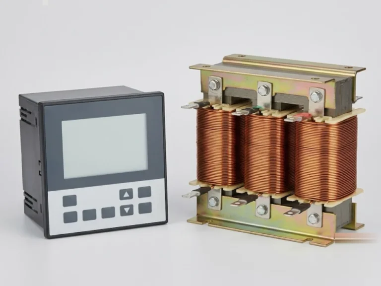
- APFC controller: reads current from a CT and voltage from the bus, calculates the kVAr shortfall and decides which steps to switch.
- Capacitor contactors: special duty contactors with pre-insertion resistors, built to survive the inrush when a capacitor is switched in. A normal motor contactor is not suitable.
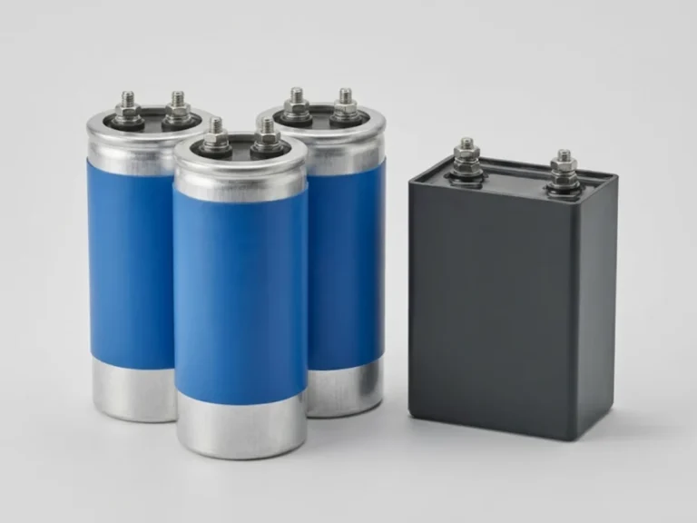
- Power capacitors: three-phase units in steps such as 5, 10, 25 or 50 kVAr.
- Detuned reactors: in series with the capacitors where harmonics are present.
- Protection: HRC fuses or MCCBs for the bank and each step, plus discharge devices.
- Cooling: fans and filters, because capacitors and reactors run warm.
Look at our APFC panel, APFC controllers and detuned reactors and power capacitors pages for the components.
Step 1: find the kVAr required
The basic formula is:
kVAr required = kW × (tan φ1 − tan φ2)
where φ1 is the present power factor angle and φ2 is the target. Use the maximum demand kW from your bills or a power analyser, not the connected load.
Worked example: a plant with a 500 kW demand at a power factor of 0.80 wants 0.99.
- tan φ1 at PF 0.80 = 0.750
- tan φ2 at PF 0.99 = 0.143
- kVAr = 500 × (0.750 − 0.143) = about 304 kVAr
So a panel of roughly 300 kVAr is needed. You can run your own numbers on our power factor calculator.
Step 2: choose the steps
The controller can only correct in whole steps, so smaller steps give finer control. A 300 kVAr panel might be built as:
| Step layout | Result |
|---|---|
| 6 steps of 50 kVAr | Simple and cheaper, coarse control |
| 2 × 25 + 5 × 50 | Better at light load, mid price |
| 1 × 10 + 2 × 20 + 5 × 50 and similar binary combinations | Fine control, more contactors and cost |
A useful rule: the smallest step should be below the kVAr the controller must trim at the lightest load, otherwise it hunts, switching a step in and out repeatedly. Controllers with 8, 12 or 14 stage outputs are common.
Step 3: decide on detuning
This step decides whether the panel lives for years or fails in months. Capacitors form a resonant circuit with the transformer. If the plant has VFDs, UPS, rectifiers, LED lighting or arc furnaces, harmonic currents (mainly the 5th and 7th) can excite that resonance and overload the capacitors.
- Standard capacitors, no reactor: only for loads that are mostly linear, such as plain induction motors, with negligible harmonic content.
- Detuned (reactor-fed) bank: a series reactor, commonly 7 percent, moves the resonance below the 5th harmonic and so protects the capacitors. A 7 percent reactor tunes the circuit to about 189 Hz on a 50 Hz system.
- Heavy-duty capacitors: a higher voltage rating (for example 440 V on a 415 V system) is used with detuned banks, because the reactor raises the capacitor voltage slightly.
As a rough guide, if the non-linear load (drives, UPS and similar) is more than about 15 to 20 percent of the transformer rating, treat the panel as one that needs detuning, and ideally measure the harmonic distortion first.
Step 4: check the practical limits
- Do not overcorrect. Leading power factor at light load can push voltage up and confuse generators. Set the target at 0.98 to 0.99 lagging rather than 1.0.
- Controller CT location. The CT must measure the whole load the bank is correcting, upstream of the capacitor connection, and its phase must match the voltage reference. A wrong CT connection is the most common reason a new panel “does not work”.
- DG operation. Banks should be locked out when the plant is on a DG set unless the alternator can take leading kVAr.
- Cable and breaker sizing. The bank breaker is sized for around 1.3 to 1.5 times capacitor rated current, to allow for harmonics and tolerance.
- Temperature. Panel ventilation matters; capacitors lose life quickly when run hot.
Why it pays back
Many DISCOMs levy a penalty or give a rebate linked to power factor, and some HT consumers are billed on kVAh, which makes low PF a direct cost. The exact tariff terms differ by state and category, so read your latest tariff order. The correction also reduces current in the transformer and cables, giving a little more headroom. Check the numbers against your actual bills before sizing for savings.
The final sizing, reactor selection and protection settings should be confirmed with a qualified engineer, ideally after a power quality log of a week or more.
What to send us for a quotation
Send the transformer rating, maximum demand in kW, present and target power factor, a note on drives or other harmonic sources, and whether the plant runs on DG. Add any harmonic measurement you have. You can request a quotation or contact us to discuss the step layout. We respond within 24 hours. The panel normally feeds from the PCC, so also see our power factor correction products.
Frequently asked questions
How do I calculate the kVAr for an APFC panel?
Use kVAr = kW x (tan of present angle minus tan of target angle). For 500 kW at 0.80 PF corrected to 0.99, that is 500 x (0.750 – 0.143), about 304 kVAr. Take kW from your maximum demand readings or a power analyser, not from the connected load, and then round to the nearest practical panel size.
Do I need detuned reactors in my APFC panel?
If your load includes VFDs, UPS, rectifiers, LED drivers or similar non-linear equipment, yes, a detuned bank is the safer choice. Plain capacitors can resonate with the transformer and fail early. If the load is almost all direct-on-line induction motors, a standard bank may be adequate, but a harmonic measurement is the best way to know.
What is the difference between a fixed capacitor bank and an APFC panel?
A fixed bank stays connected all the time and suits a steady load. An APFC panel has a controller that switches capacitor steps in and out to follow a changing load. Without that control, a fixed bank overcorrects at light load, which can cause leading power factor and voltage rise.
Why is my APFC panel not switching capacitors?
The usual causes are a wrongly placed or wrongly phased CT, a controller target set beyond what is needed, a trip of the bank breaker or fuse, or the DG lockout being active. Checking the CT polarity and location against the controller manual is the first step, followed by the step contactors and fuses.