Earthing does two jobs that cannot be skipped. It keeps the metal parts of equipment at a safe voltage so that a person touching them during a fault is not shocked, and it gives fault current a low-impedance path back to the source so that breakers and fuses operate quickly. A plant with poor earthing may run for years without trouble and then fail on the one day it matters. This guide covers the physical parts of an industrial earthing system and the points that decide whether it works.
What IS 3043 covers, in general terms
IS 3043 is the Indian code of practice for earthing. In general terms it deals with the purposes and terminology of earthing, the earthing of systems (neutral earthing) and of equipment (protective earthing), the design and selection of electrodes and earth conductors, soil resistivity and its effect, measurement of earth resistance, touch and step voltage considerations, earthing of substations and special installations, and maintenance. It is a code of practice and not a purchase specification, so read the current edition and your project specification together. The detailed values and clause-level rules should be confirmed by a qualified engineer from the standard itself.
The parts of an earthing system
Earth electrodes
The electrode is the part buried in the soil. Common types:
- Pipe electrode. A galvanised iron (GI) pipe, typically about 3 m long with a diameter of 40 to 50 mm class, driven vertically with a funnel at the top for watering. The classical choice for plant earthing.
- Plate electrode. A GI or copper plate buried vertically, with a pit around it.
- Rod electrode. A copper or copper-bonded steel rod driven into the ground. It is used where the soil permits deep driving and low maintenance is wanted.
- Strip and conductor electrodes. A buried strip or wire laid horizontally in a trench, useful in rocky ground and as part of a ring or mesh.
- Chemical earthing electrodes. A hollow copper or GI electrode filled with a salt or chemical compound, with the earth enhancement compound around it, used where soil resistivity is high or space is small.
Our earthing materials (earth pits, electrodes and strips) cover these items.
Earth pit
The pit is the arrangement of electrode, backfill, a connection point and an inspection cover. A typical GI pipe pit has a charcoal and salt layer or a low-resistance compound around the electrode, a watering funnel with a cover and a test link above for disconnection and measurement. The filling material keeps contact with the soil moist and conductive. Poorly maintained filling is one reason pit resistance rises in dry months.
Strips and conductors
Earth strips connect the electrodes to the equipment. GI strips (for example 25 x 5 mm to 50 x 6 mm) or copper strips run in trenches or on the wall and are bolted or welded to the earthing points. Cross-section is chosen from the fault current and its duration, using the usual heating formula for the material, and then checked for mechanical strength and corrosion allowance. Your engineer should calculate it, not copy a size from another plant. See cable accessories and earthing for lugs, strips and accessories.
Choosing material: GI, copper or copper-bonded
| Material | Strengths | Watch out for |
|---|---|---|
| GI (galvanised steel) | Low cost, widely used, suited to plant earth grids | Corrodes in aggressive soils; zinc coating lasts a limited time |
| Copper | Excellent conductivity, long life, resists corrosion | Higher cost, theft risk; do not couple directly to steel buried nearby without thought, since galvanic corrosion can accelerate loss of the steel |
| Copper-bonded steel | Strength of steel with a copper surface; good for driven rods | Damage to the copper layer during driving exposes the steel |
| Stainless steel | Corrosion resistant in some environments | Higher cost; check conductivity and connection compatibility |
Soil resistivity decides the design
Earth resistance depends mostly on the soil, not the metal. Sand, rock and dry laterite have high resistivity; moist clay and black cotton soil are lower. Before designing, measure soil resistivity at the site, ideally by the Wenner four-point method, and in more than one season if possible. If resistivity is high, you can lower resistance by using more electrodes in parallel (spaced apart by at least about the electrode length, so their zones do not overlap), a deeper electrode, an earth enhancement compound or a mesh. Adding a second electrode right next to the first helps much less than people expect.
Plant earthing: ring, mesh and separate systems
- Ring or grid. A buried conductor loop around the substation and plant, with spurs to equipment, so any point is connected in two directions. This gives lower impedance and better step and touch voltage control.
- Equipotential bonding. All metal structures, cable trays, panel frames and pipes are bonded to the earth grid.
- Separate earth for electronics. Some control and instrument systems are specified with a separate clean earth, joined to the main grid at one point as per the project design. Do not create isolated earths without a design.
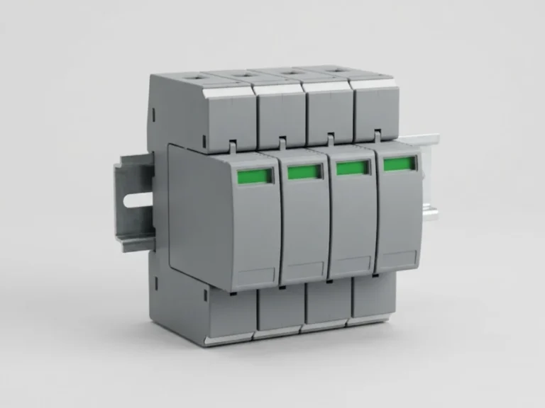
- Lightning and surge. The lightning protection down conductors and surge protection earth are connected to the same low-impedance grid as per the design. See surge protection devices.
- Neutral earthing. Transformer and generator neutrals are earthed at the source, directly or through a resistor (see neutral grounding resistor panels).
Testing and maintenance
- Measure earth resistance on commissioning, with the pit disconnected from the grid using the test link, by the fall-of-potential method or a suitable earth tester. Clamp-on testers help on connected grids.
- Repeat at regular intervals and in the dry season. Many plants test at least annually, and critical installations more often.
- Water GI pipe pits as required, and check connections and corrosion at joints.
- Record the readings in a log so that rising resistance is noticed early.
Target values depend on the installation type. Large substations and generating stations are designed to a low value, commonly of the order of one ohm or less, while smaller installations accept higher values according to the code and the protection scheme used. Take the numeric target from the project specification and the applicable code, not from a general article.
Common mistakes
- Putting the pit too close to a building foundation, a tree or a pipe route, or in a spot that dries out.
- Poor bolted joints, uncoated joints and buried strip joints without protection against corrosion.
- Strip size copied without a fault calculation.
- Mixing copper and GI conductors without isolating the junction against galvanic corrosion.
- No test link, so the electrode cannot be measured on its own.
What to send us for a quotation
Send the number of pits you need, electrode type (GI pipe, plate, copper rod or chemical), strip size and length, soil report if available, and any specification clause. Use request a quote or contact us. Please have the earthing design and safety-critical values confirmed by a qualified engineer.
Frequently asked questions
What does IS 3043 cover?
IS 3043 is the Indian code of practice for earthing. In general terms it covers system and equipment earthing, electrodes and earth conductors, soil resistivity, earth resistance measurement, touch and step voltage, substation earthing and maintenance. Read the current edition with your project specification and have a qualified engineer confirm the design.
What is the difference between GI and copper earthing?
GI is cheaper and common in plant grids but corrodes over time, depending on soil. Copper conducts better and lasts longer but costs more and is a theft target. Copper-bonded rods give a middle path. The right choice depends on soil, budget, fault level and the life you expect.
How often should earth pits be tested?
At commissioning, and then at regular intervals, commonly at least once a year and more often for critical installations. Test in the dry season when resistance is highest. Disconnect the pit using the test link and record readings so that a rising trend is noticed. Follow the schedule in your site safety practice.
When is chemical earthing useful?
Chemical earthing helps where soil resistivity is high, space is limited, or maintenance of watering pits is difficult. The electrode is surrounded by an enhancement compound that keeps resistance more stable through seasons. It is not a cure for poor design, so measure soil resistivity and check the result with a qualified engineer.