APFC Controllers & Detuned Reactors
APFC Controllers & Detuned Reactors
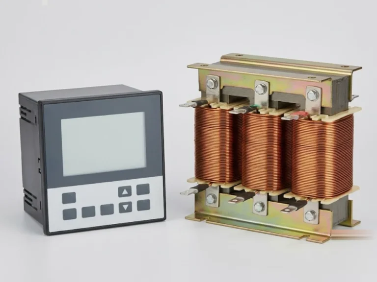
Automatic power-factor controllers and detuning reactors used in APFC panels.
- StandardIEC 61000-6, IS 5553 (reactors)
Power Factor
Browse the full range. Filter by category or feature, compare specifications and add items to your quote list.
Automatic power-factor controllers and detuning reactors used in APFC panels.
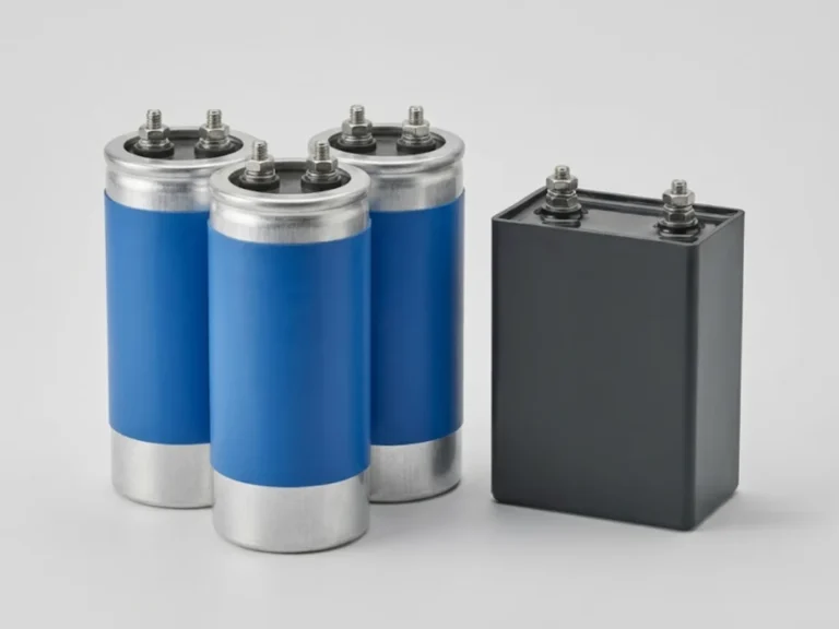
LT power capacitors for power-factor correction, in cylindrical and box constructions.
No products match your filters. or ask our engineers.
Power factor correction equipment supplies reactive power locally so the transformer and cables carry less current. This category lists power capacitors and APFC controllers and detuned reactors, which are assembled into an APFC panel for automatic correction.
The capacitor kVAr needed equals the real power in kW multiplied by the difference between the tangents of the existing and target power factor angles. For a 500 kW load, raising power factor from 0.80 to 0.98 needs roughly 500 x (0.75 - 0.20) = 275 kVAr. As the load changes through the day, the total is split into steps and switched by a controller.
The decision that matters most is harmonics. Drives, UPS and LED lighting produce harmonic currents, and a plain capacitor can resonate with the transformer inductance, overheat and fail. A detuned reactor in series with the capacitor shifts the resonance below the dominant harmonic, commonly 7 percent reactance (about 189 Hz) where fifth harmonic dominates and 14 percent where third harmonic is significant. Checklist:
Estimate the size with the power factor calculator and monitor the result with metering. Capacitors can hold charge after switch-off, so discharge them and follow isolation procedures.
A plain capacitor bank has only capacitors and suits loads with little harmonic content. A detuned bank puts a reactor in series with each capacitor step to prevent resonance with the network and to absorb some harmonic current. Where drives, UPS or LED lighting form a large share of the load, detuned banks are the safer choice.
Use kVAr = kW x (tan of existing angle minus tan of target angle). For 200 kW going from 0.85 to 0.98 power factor, that is about 200 x (0.62 - 0.20) = 84 kVAr. Measure kW at typical and peak load, then pick standard steps. The power factor calculator on this site gives a quick estimate.
Drives draw non-sinusoidal current, so harmonics flow into the network. A capacitor lowers the system resonance frequency, and if that lands near a dominant harmonic, current and voltage amplify, overheating and damaging the capacitor. Detuned reactors, correct capacitor voltage rating and a harmonic survey prevent this.
APFC means automatic power factor correction. A controller measures the system power factor using a CT, and switches capacitor steps in or out through contactors to hold the target value as the load changes. This avoids both low power factor at high load and leading power factor at light load.
Many tariffs reward or require power factor around 0.95 or above, with some reaching up to unity incentives, but rules vary by state and DISCOM. Setting a very high target can lead to leading power factor at light load, so many users set 0.97 to 0.99. Check your tariff order and electricity bill.
What power factor is, how it affects your DISCOM bill and transformer loading, and how to size and select capacitors, APFC controllers and detuned reactors for…
6 min readTransformers & Power QualityA step-by-step method to size a 11 kV/415 V transformer for a factory or building, with a worked example, standard kVA ratings and the mistakes that…
6 min readSwitchgear, Panels & ProtectionAn APFC panel switches capacitor banks automatically to hold power factor near unity. Here is how to work out the kVAr, the steps and the detuning…
6 min read