A protection relay watches current and voltage from CTs and PTs and decides when to trip a breaker. It is the brain between the measuring transformers and the circuit breaker. When it works as intended, a fault is cleared in milliseconds to a fraction of a second and the damage stays small. When it is wrongly set or wrongly wired, a minor fault can burn a motor, a cable or a whole panel. This overview explains the three most common relay families in industrial plants and how to choose between them.
The chain: CT, relay, breaker
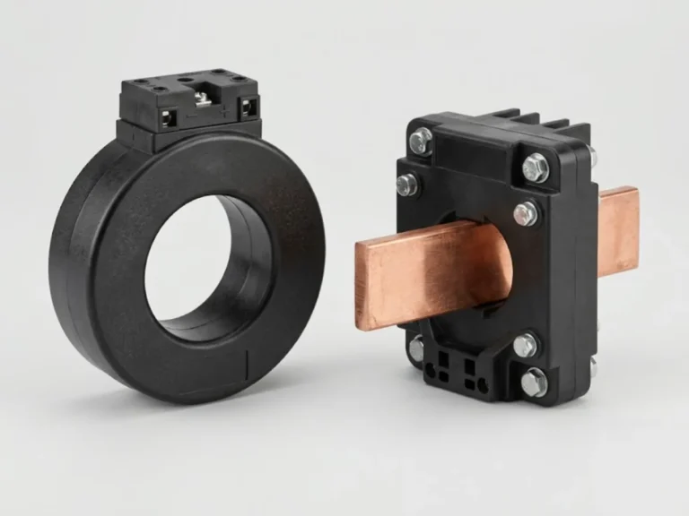
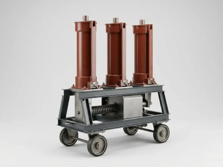
The relay does not measure primary current directly. A current transformer scales it down to 1 A or 5 A, the relay compares it with its settings, and if a limit is exceeded it closes a trip contact that energises the shunt trip or trip coil of a breaker. That breaker may be a VCB on a medium-voltage panel, an ACB on a low-voltage incomer, or a contactor for a motor. A trip supply (DC battery, capacitor trip or UPS) must also be available. See our instrument transformers and protection category.
Overcurrent protection (50/51)
Overcurrent relays protect against overload and short circuits. In the ANSI device numbering used worldwide, 51 is the time-delayed overcurrent element and 50 is the instantaneous element.
- Pickup (current setting): the current above which the relay starts timing. It is set above the normal maximum load, including permitted overload and transformer inrush, and below the minimum fault current at the end of the protected section.
- Time setting: how long the relay waits. IDMT (inverse definite minimum time) curves, such as normal inverse, very inverse and extremely inverse, make the trip time shorter as the current increases. Definite-time settings trip after a fixed delay.
- Instantaneous element: trips with no intentional delay for very high currents, typically close to the relay’s own breaker. It must be set to avoid tripping for faults on the next downstream device.
Coordination (“grading”) is the real design task. The relay nearest the fault must operate first and the upstream relay should wait, with a time margin that covers breaker opening time and relay errors. A common allowance is in the range of 0.3 to 0.5 seconds per level, but your own study will fix it. Relay settings in a plant should be set from a short-circuit and coordination study by a qualified engineer.
Earth fault protection (50N/51N)
An earth fault relay responds to current flowing to earth. Most faults in industrial plants start as earth faults, so sensitivity matters.
- Residual connection: three phase CTs are connected so that the sum of the three currents is measured. In a healthy system this sum is close to zero.
- Core balance CT (CBCT): a single ring CT surrounds all the cables of a feeder, and measures only the unbalance. It gives high sensitivity and is the preferred method for motor feeders and cables.
- Neutral CT: a CT in the transformer neutral earthing path for restricted earth fault or standby earth fault protection. This relates to how the neutral is earthed, including through a neutral grounding resistor.
The earth fault setting is usually much lower than the phase setting, which is why earth fault elements are typically separate from phase elements. In a solidly earthed LV system the earth fault current can be high; with resistance earthing the current is limited to a design value and the relay must be set below it.
Motor protection
A motor sees more types of abnormality than a feeder, so motor protection relays combine several functions.
| Function | What it protects against |
|---|---|
| Thermal overload (49) | Overheating due to overload; a thermal model tracks heat based on current over time |
| Locked rotor / stall (48/51LR) | Motor fails to accelerate or stalls while running |
| Short circuit (50) | Phase-to-phase faults |
| Earth fault (50N/51N) | Insulation failure to earth |
| Phase unbalance / negative sequence (46) | Single phasing and supply imbalance, which heat the rotor |
| Undercurrent (37) | Dry running of pumps, belt breakage, loss of load |
| Too many starts (66) | Overheating from repeated starts |
| RTD / PTC input | Winding and bearing temperature sensors |
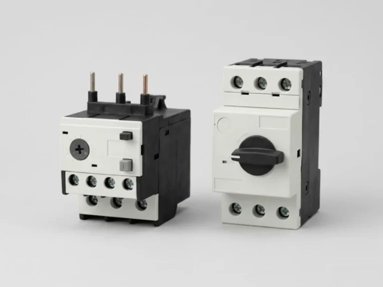
For small LV motors, protection is often a thermal overload relay or MPCB with a contactor. For larger and critical motors, especially at 3.3 kV, 6.6 kV and 11 kV, a numerical motor protection relay is used. Check the starting current and starting time of the motor, which must be set so the relay does not trip during a normal start. Related products include drives and motor starters and motors.
Other functions you will meet
- Under and over voltage (27/59) and frequency (81). Supply quality monitoring.
- Directional overcurrent (67). For ring networks and parallel feeders.
- Differential (87). For transformers, large motors and generators, it compares current into and out of the equipment and trips only for internal faults. It needs matching CTs and sometimes vector group compensation.
- Lockout (86). Holds the trip until reset by an operator.
- Transformer mechanical devices. The Buchholz relay, oil and winding temperature indicators and pressure relief valve trip the transformer breaker directly.
Electromechanical versus numerical relays
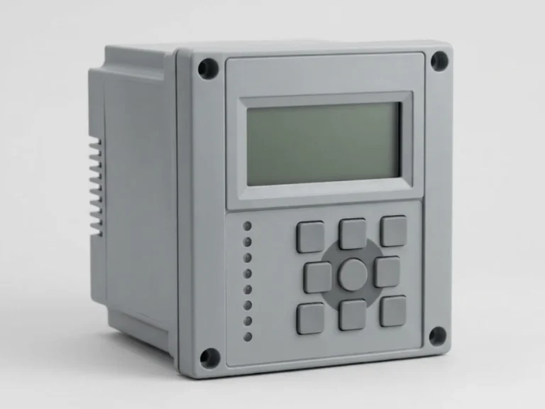
Older electromechanical relays have one function each and are adjusted with dials. Numerical (microprocessor) relays combine many functions in one device, with setting groups, event recording, disturbance records and communication ports (such as Modbus or IEC 61850). They also show measured current and fault records, which makes fault analysis much easier. For new panels the numerical type is the normal choice. For replacement work in an old panel, check the cut-out size, terminal arrangement and CT ratio. See the protection relays range and relays in general.
How to choose a relay
- What is being protected: feeder, transformer, motor, generator, capacitor bank?
- Which functions are needed (50/51, 50N/51N, 49, 46, 87, 27/59)?
- CT secondary (1 A or 5 A) and relay burden; confirm the CT class suits the relay.
- Auxiliary supply: DC or AC/DC universal, and voltage.
- Number of binary inputs and output contacts for trip, alarm, interlocks.
- Communication needs: SCADA, plant network.
- Mounting: flush in a panel door or draw-out case.
Remember that the relay is only as good as its settings and its test records. Periodic secondary injection testing proves the relay and the trip circuit, including the breaker.
What to send us for a quotation
Send the equipment to be protected, voltage, CT ratio and class, functions needed, auxiliary supply, communication protocol and the single-line diagram if available. Submit through request a quote or contact us. Settings and coordination are safety-critical, so please have them confirmed by a qualified protection engineer.
Frequently asked questions
What is the difference between overcurrent and earth fault relays?
An overcurrent relay responds to excessive phase current from overload or short circuit. An earth fault relay responds to current leaking to earth, which is usually much smaller, so it has a lower and more sensitive setting. Many numerical relays combine both in a single device.
What does IDMT mean in a relay?
IDMT stands for inverse definite minimum time. The higher the fault current, the shorter the trip time, down to a minimum limit. Curves such as normal inverse, very inverse and extremely inverse allow upstream and downstream relays to be coordinated so the device closest to the fault trips first.
Is a thermal overload relay enough for a motor?
For small LV motors, a thermal overload relay or MPCB with a contactor is common practice. Larger or critical motors, especially at medium voltage, usually need a numerical motor protection relay with thermal model, stall, unbalance, earth fault and start-count functions. Choose according to motor size and consequence of failure.
What information is needed to set a protection relay?
You need the equipment ratings, CT ratio, maximum load current, motor starting current and time, fault levels, the settings of upstream and downstream devices and the earthing arrangement. A coordination study then gives the pickup and time settings. Have a qualified protection engineer set and test them.