Instrument Transformers & Protection
Current Transformers (CT)
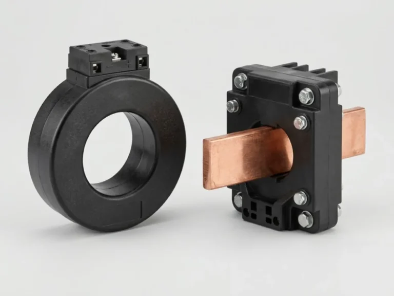
Current transformers that step down primary current for meters and protection relays.
- StandardIS 2705 / IEC 61869-2
Circuit Protection
Browse the full range. Filter by category or feature, compare specifications and add items to your quote list.
Current transformers that step down primary current for meters and protection relays.
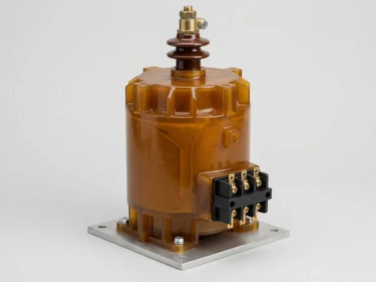
Voltage transformers for metering and protection at medium and high voltage.
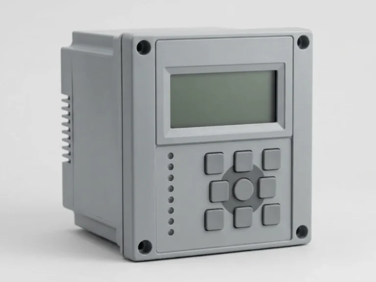
Numerical and electromechanical protection relays for feeders, motors, generators and transformers.
No products match your filters. or ask our engineers.
This group links the power system to the protection and metering that watch it. It includes current transformers, potential (voltage) transformers and protection relays for overcurrent, earth fault and motor protection, used in LV panels, MV switchgear, transformers and motor feeders.
A CT steps a large primary current down to 1 A or 5 A for relays and meters; a VT does the same for voltage, commonly to 110 V. Never leave a CT secondary open-circuit while the primary carries current, because the voltage across the open winding becomes dangerous. Short the terminals first.
When selecting CTs and VTs:
On protection relays, define the functions first: IDMT overcurrent, instantaneous, earth fault, thermal and locked-rotor motor protection, then the settings that suit the upstream and downstream devices. Settings should come from a coordination study by a qualified engineer. Relevant standards are IS 2705 for CTs, IS 3156 for VTs and the IEC 60255 series for relays. The relay trips circuit breakers and often shares its CT with meters.
It is a protection class. The first number, 5, is the composite error limit in percent at the accuracy limit current, P stands for protection, and 10 is the accuracy limit factor, so the CT stays within 5 percent error up to 10 times its rated current. A higher factor, like 5P20, keeps accuracy at higher fault currents.
With the primary carrying current and the secondary open, no opposing flux exists, so the core saturates and a very high voltage appears across the secondary terminals. This can destroy insulation and is a shock hazard. Always short the secondary terminals before removing a meter or relay from a live CT circuit.
Instantaneous protection trips without intentional delay when current exceeds a set value. IDMT, inverse definite minimum time, trips faster as current rises, giving time grading with other devices. Most overcurrent relays offer both: IDMT for coordination and an instantaneous element for severe faults close to the relay.
Add the burden of every connected relay and meter, plus the lead resistance, which depends on cable length and cross-section. The CT's rated burden should be equal to or higher than this total. A burden that is too high saturates the CT early and a very low burden wastes cost. Using a 1 A secondary reduces lead loss on long runs.
Provide the equipment protected (feeder, motor, transformer), the protection functions required, CT and VT ratios, auxiliary supply voltage, number of contact outputs, and communication protocol. A single line diagram helps. Relay settings should be derived separately from a coordination study by a qualified protection engineer.
A practical overview of overcurrent, earth fault and motor protection relays: what each function does, how IDMT curves and grading work, and what to specify when…
7 min readTransformers & Power QualityPlain-language guide to current and potential transformers: ratio, burden, accuracy class for metering and protection, 1 A versus 5 A secondaries, and the mistakes that cause…
7 min read