A plant engineer usually meets harmonics through their effects rather than their name: a capacitor bank that keeps blowing fuses, a neutral conductor that runs hot, a transformer warmer than its load suggests, drives that trip for no clear reason. All of these can trace back to distorted current and voltage waveforms. This guide explains harmonics in plain terms and shows how to find and handle them, without the heavy mathematics.
SKE Bharat supplies the equipment mentioned here: power analysers, capacitors, detuned reactors, APFC panels, drives and protection. Choosing a filter or reactor rating depends on measurements from your own plant, so have a qualified power quality engineer confirm the design.
What harmonics are
In an ideal supply, voltage and current are smooth sine waves at 50 Hz. A non-linear load draws current in pulses instead, so its current is not a sine wave. Any distorted wave can be described as the sum of the 50 Hz fundamental and extra waves at whole-number multiples of it. These extra waves are harmonics: 150 Hz is the 3rd, 250 Hz the 5th, 350 Hz the 7th, and so on.
The current harmonics flow through the source impedance, which includes your transformer and cables, and create voltage distortion. That distorted voltage then reaches every other load on the same bus.
Where they come from
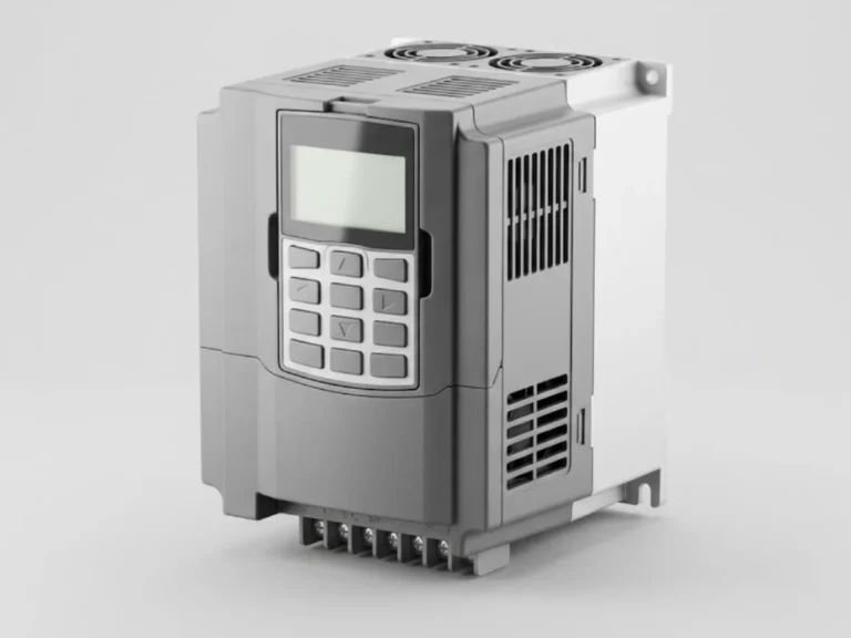
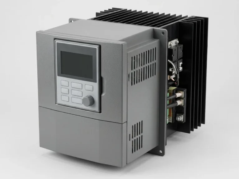
- Variable frequency drives and DC drives. Six-pulse rectifiers produce mainly 5th, 7th, 11th and 13th harmonics. See AC drives and DC drives.
- UPS systems and battery chargers with rectifier input stages.
- SMPS loads: computers, LED drivers and office equipment. In large numbers, these load the neutral heavily with 3rd harmonics.
- Welding machines, induction and arc furnaces and other irregular loads.
- Inverters, including solar inverters, usually have low harmonic output but are not zero.
Symptoms that point to harmonics
| Symptom | Possible harmonic link |
|---|---|
| Capacitor fuses blow, capacitors bulge or run hot | Capacitors act as a path for harmonic current; resonance can magnify it |
| Neutral conductor overheating in a 3-phase 4-wire system | 3rd harmonic currents add in the neutral instead of cancelling |
| Transformer hotter than expected for its loading | Harmonic currents increase losses |
| Nuisance tripping of breakers or drives | Peak currents and distorted voltage affect protection and electronics |
| Motors running warm or noisy | Harmonic voltage adds heating and torque ripple |
| Meters, PLCs or controls misbehaving | Distorted supply and noise on the system |
These symptoms can also have other causes, so confirm by measurement.
How to measure
Two numbers are widely used. THD of voltage (THD-V) shows how distorted the supply voltage is. THD of current (THD-I) shows how distorted a load’s current is, but it can mislead at light load because a small current with a large distortion percentage may be harmless. Standards such as IEEE 519 also express current distortion relative to the maximum demand current of the plant. Check which limits your utility or contract requires.
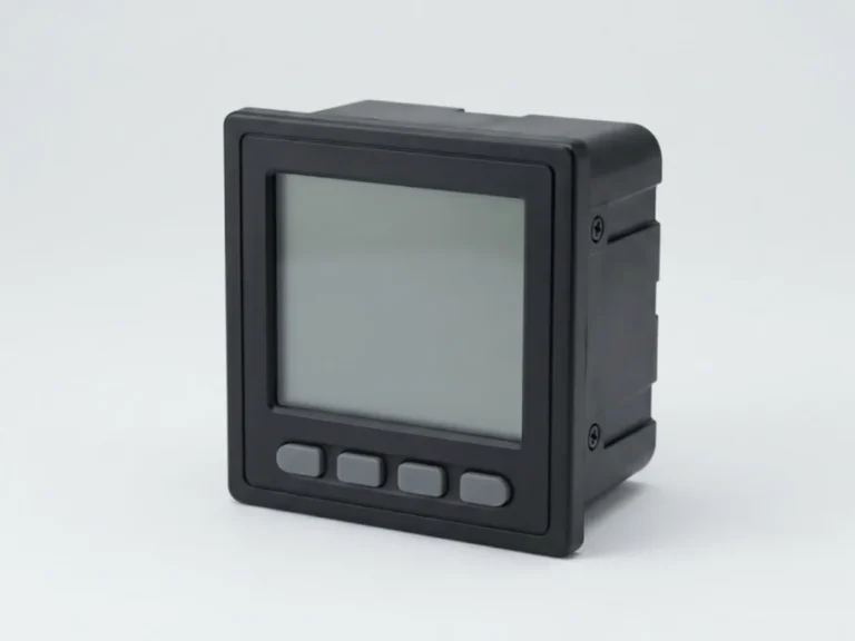
- Use a power analyser that logs harmonics, not just a handheld reading.
- Measure at the point where the supply enters your plant (the point of common coupling), at the incomer of any capacitor bank, and at the large non-linear loads.
- Log for at least a representative week including typical production and also periods of light load, since resonance problems often appear when part of the load is off.
- Record individual harmonic orders, not only total THD. A bank tuned wrongly causes trouble when it lines up with a specific order.
Capacitor banks and resonance
This is the most expensive harmonic problem in many plants. A capacitor and the transformer inductance form a resonant circuit. If its resonance frequency lands near a harmonic that your drives produce, such as the 5th or 7th, the harmonic current is amplified and the capacitors suffer.
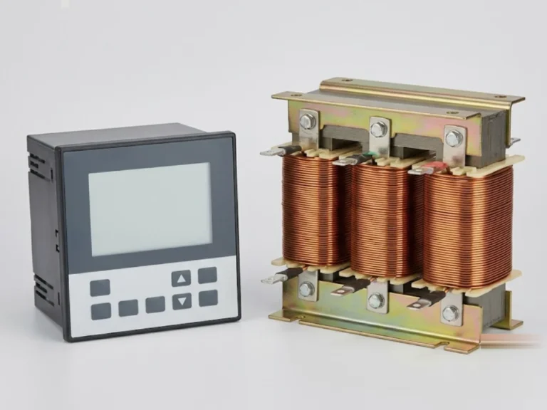
The standard answer is a detuned capacitor bank: each capacitor stage is put in series with a reactor, which moves the resonance well below the lowest significant harmonic. Reactors tuned at around 189 Hz (7 per cent) or 210 Hz (about 5.67 per cent) are commonly used on 50 Hz systems, but the choice depends on the harmonic spectrum measured. Where harmonic content is high, a detuned bank may need capacitors with a higher voltage rating. See APFC controllers and detuned reactors, power capacitors and APFC panels. For power factor sizing use the power factor calculator.
Reducing harmonics
- Line or DC-link reactors on drives. A simple, low-cost measure that reduces current distortion.
- Higher-pulse or active front-end drives for large drive loads.
- Passive tuned filters for specific harmonic orders from large fixed loads.
- Active harmonic filters that inject opposing current; useful where load is varied and wide-spectrum.
- Transformer and neutral measures: derating or specially designed transformers for harmonic-rich loads, a neutral conductor sized for 3rd harmonic currents, and separate transformers or feeders for sensitive loads. See transformers.
- Layout: keep non-linear loads at a common bus away from sensitive equipment where possible.
Other power quality problems
- Voltage sags and interruptions that trip drives and contactors. Consider online UPS for controls.
- Surges and transients from switching and lightning. Fit surge protection devices.
- Phase unbalance that overheats motors.
- Low power factor that raises costs.
Continuous measurement helps catch these early; see energy monitoring in factories.
What to send us for a quotation
Send your transformer rating and impedance, the power analyser log if available, a list of drives and other non-linear loads with ratings, the present capacitor bank details, and the target power factor. Use request a quote or contact us; we respond within 24 hours.
Frequently asked questions
What causes harmonics in an industrial plant?
Non-linear loads that draw current in pulses rather than smooth sine waves. Common sources are variable frequency drives, DC drives, UPS and battery chargers, switch-mode power supplies, LED drivers, welding machines and furnaces. Their distorted current flows through the transformer and cables and distorts the voltage seen by other equipment.
Why do capacitor banks fail in plants with VFDs?
A capacitor bank and the transformer inductance can resonate near a harmonic frequency such as the 5th or 7th produced by drives. The harmonic current is then amplified through the capacitors, overheating them and blowing fuses. Detuned banks with series reactors move the resonance away from these harmonics and protect the capacitors.
What is the difference between THD-V and THD-I?
THD-V is the distortion of the supply voltage, which affects all equipment on the bus. THD-I is the distortion of a load's current, and it can look high at light load even when the actual harmonic current is small. Standards such as IEEE 519 relate current distortion to the plant's maximum demand current.
Do I need an active harmonic filter or are reactors enough?
It depends on measurements. Line reactors on drives and detuned capacitor banks handle many plants. Active filters suit plants with large, varying non-linear loads or strict limits. Log harmonics at the incomer and at the main drive feeders first, and have a power quality engineer recommend the solution.