A direct-on-line starter has three jobs: switch the motor on and off, protect it against overload, and survive a short circuit in the cable or windings without becoming a fire hazard. That takes three devices working together: a contactor for switching, an overload relay for slow overloads, and a short-circuit protective device (MCCB, MPCB or fuse). This article covers how to pick the contactor and overload relay, and how to match them to the third.
Step 1: start from the motor full load current
Take the full load current (FLC) from the motor nameplate. If you only have the kW, an estimate for a 415 V, 3-phase induction motor is:
I = (kW × 1000) / (√3 × 415 × power factor × efficiency)
Example: a 37 kW motor at PF 0.88 and efficiency 0.93 gives about 37,000 / (1.732 × 415 × 0.88 × 0.93) = about 63 A. Nameplates for such motors commonly read between 62 and 70 A, so use the actual plate value. You can check the numbers with our motor current and cable calculator.
Step 2: choose the contactor by utilisation category
Contactors are rated by what they switch, not only by current. The category comes from IEC 60947-4-1.
| Category | Duty | Typical use |
|---|---|---|
| AC-1 | Non-inductive or slightly inductive load | Heaters, resistive loads |
| AC-3 | Starting squirrel-cage motors and switching them off while running | Pumps, fans, compressors, conveyors |
| AC-4 | Starting, plugging and inching | Cranes, hoists, frequent reversing |
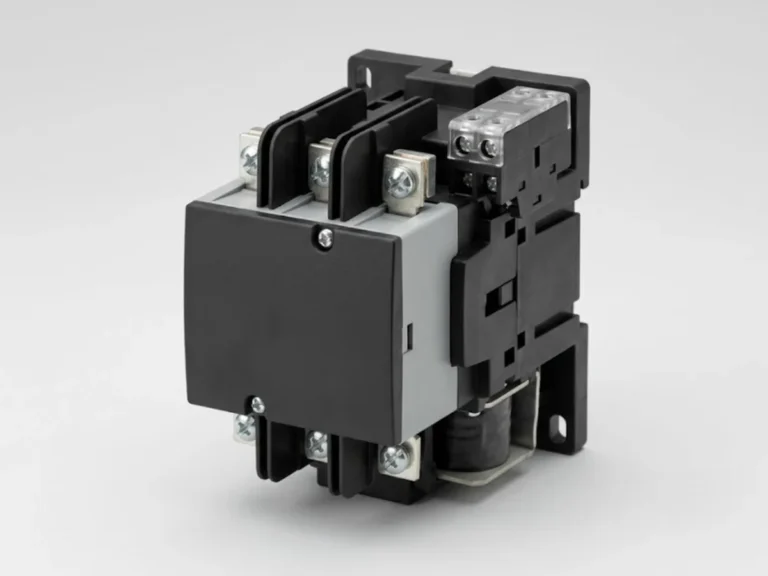
For normal motors, choose a contactor whose AC-3 rating at 415 V is equal to or above the motor FLC. For the 63 A example above, a 65 A or 80 A AC-3 contactor would be typical. Compare the AC-3 current, not the AC-1 “thermal” current printed on the front; the AC-1 figure is much higher and misleads buyers.
Move up one or two sizes, or to AC-4 rating, when the motor starts and stops very often, plugs (reversal by counter-current), inches, or drives a high-inertia load. The contactor’s electrical life falls rapidly with switching frequency.
Step 3: coil voltage and auxiliary contacts
- Coil voltage: 230 V AC, 110 V AC, 24 V AC or 24 V DC are the usual choices. Match the control circuit; do not mix. Keep the coil supply within the permitted pick-up window (typically 85 to 110 percent of rated coil voltage).
- Auxiliary contacts: one normally open contact for the hold-in (seal-in) circuit, and spare for indication and interlocks. Add blocks if the contactor lacks enough.
- Mechanical interlock: for reversing and star-delta starters, fit a mechanical interlock between contactors, as well as electrical interlocking.
See our power contactors page.
Step 4: set up the overload relay
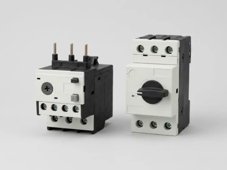
A thermal overload relay or electronic overload relay watches motor current and trips the contactor when current stays above the setting for long enough to heat the windings.
- Range: pick a relay whose adjustable range includes the motor FLC, ideally with the FLC in the middle of the range.
- Setting: set it to the nameplate FLC (or to the service factor-adjusted value if the motor is designed for it). Do not set it high “to stop nuisance trips”; investigate why it trips.
- Trip class: Class 10 trips within 10 seconds at 7.2 times the setting and suits normal-start motors. Class 20 (20 seconds) suits motors with longer starting times such as fans and centrifuges. Class 30 is for very heavy starts.
- Phase failure sensitivity: choose a relay with differential or phase-loss protection to catch single-phasing, a common cause of burnt-out windings.
- Reset: manual reset is preferred for safety. Auto-reset is risky on equipment that may restart unexpectedly.
For motors with PTC thermistors or high-duty applications, use an electronic motor protection relay instead. See thermal overload relays and MPCBs.
Step 5: coordinate with the short-circuit device
The contactor and overload relay cannot interrupt a short circuit. The upstream MCCB, MPCB or HRC fuse does that, and the three must be matched so that a fault does not weld the contactor.
- Type 1 coordination: after a short circuit, damage to the starter is accepted, as long as it causes no danger. Parts may need replacing.
- Type 2 coordination: after a short circuit, only light contact welding that is easily separated is allowed; the starter can go back into service. Use this for critical drives.
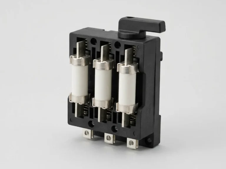
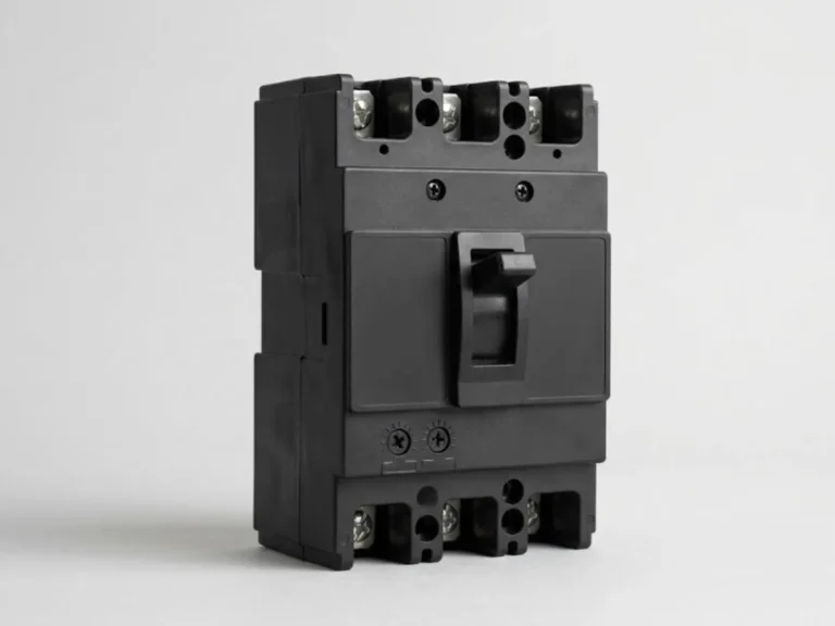
Use the manufacturer’s coordination tables for the exact combination, which list the fuse or breaker, contactor and overload relay tested together. Do not assume a breaker with the right amp rating will coordinate. Options include HRC fuses and MCCBs.
Star-delta starters
A star-delta starter uses three contactors (main, star, delta) and one overload relay. The main and delta contactors carry line current divided by √3 in delta, about 58 percent of line current, so they can be smaller; the star contactor carries even less and is usually one size smaller. The overload relay sits in the motor winding circuit, so it is set to the line FLC divided by √3 when connected that way. Check the manufacturer’s recommendation for the exact connection, as practice differs.
Typical mistakes
- Choosing the contactor by kW without checking duty category and switching frequency.
- Overload relay range far above motor FLC, giving poor protection.
- Buying cheap contactors for capacitor switching. Capacitors need special-duty contactors.
- Ignoring ambient temperature inside the panel, which reduces the contactor and relay performance and shifts the relay trip point.
Starter selection is a protection decision. Confirm final ratings, settings and coordination with a qualified engineer against the motor data and the available fault level. For soft starting see soft starters.
What to send us for a quotation
Send the motor kW, voltage, FLC, starting method (DOL, star-delta, soft starter), number of starts per hour, control voltage, and the fault level at the panel. You can request a quotation or contact us. We answer quotation requests within 24 hours.
Frequently asked questions
How do I select a contactor for a 37 kW motor?
Find the nameplate full load current, about 62 to 70 A at 415 V, then choose a contactor with an AC-3 rating at 415 V equal to or above that, commonly 65 A or 80 A. Check switching frequency and duty, and match it with the right overload relay and short-circuit protection using the manufacturer's coordination tables.
What current should I set on the overload relay?
Set it to the motor nameplate full load current, adjusted for service factor only if the motor is designed for it. Setting it higher to stop trips leaves the motor unprotected. If the relay trips repeatedly at the correct setting, look for a mechanical overload, low voltage, phase imbalance or a failing bearing.
What is the difference between Class 10 and Class 20 overload relays?
The class is the maximum time a relay takes to trip at 7.2 times its setting from a cold state: Class 10 within 10 seconds, Class 20 within 20 seconds. Class 10 suits normal-start motors. Class 20 suits loads with long accelerating times, where Class 10 would trip during a normal start.
What is Type 2 coordination?
Type 2 coordination means that after a short circuit the contactor and overload relay remain fit for service, apart from easily separated light contact welding. It is stricter than Type 1, which allows damage as long as it is safe. Use Type 2 for critical drives where downtime is costly.